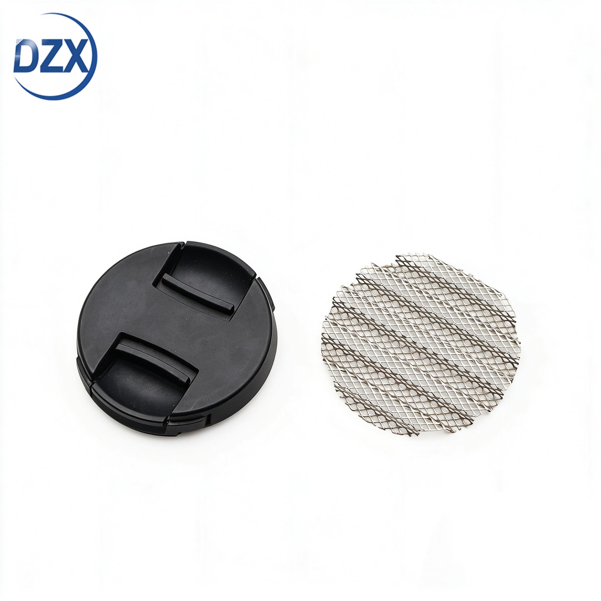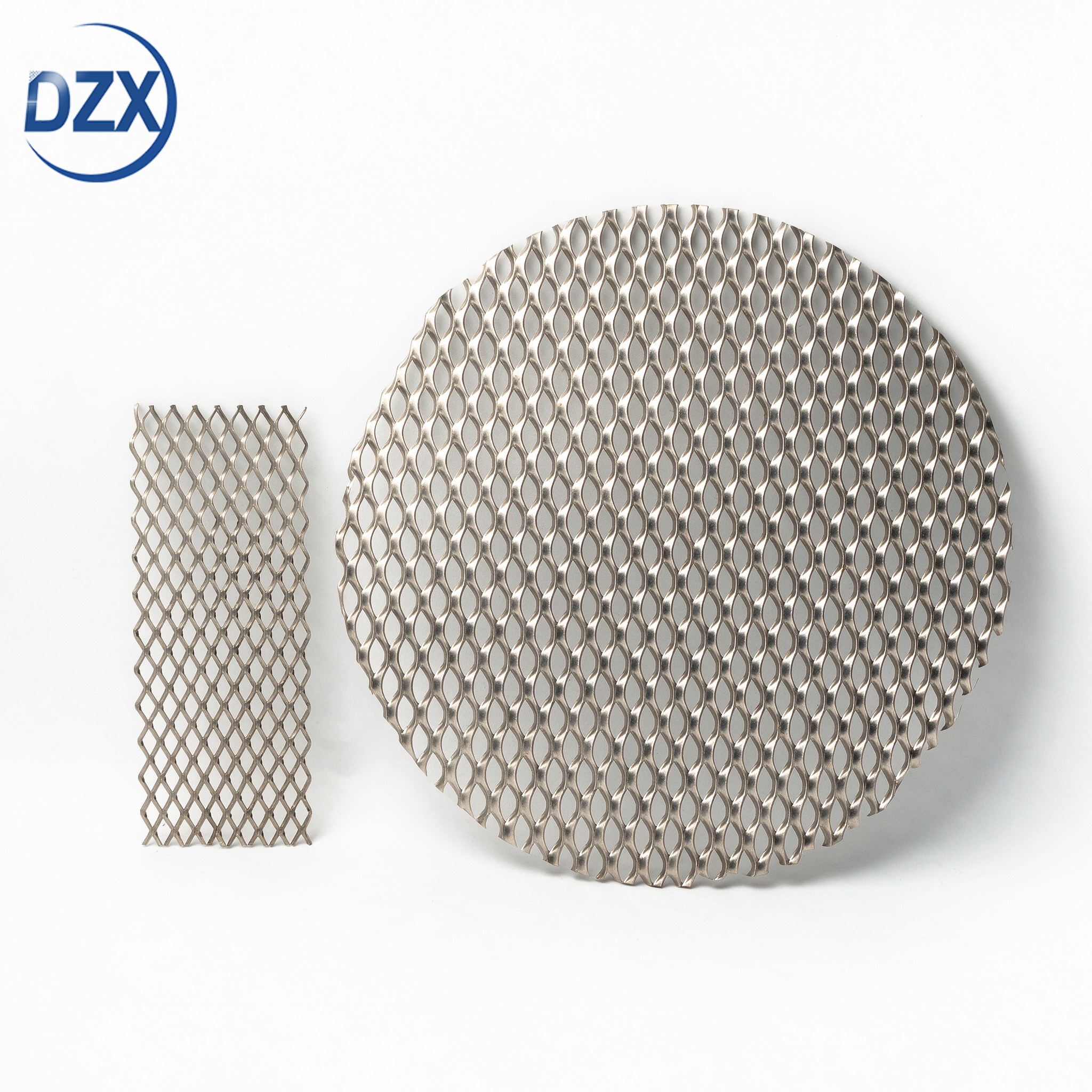


Pure Nickel Corrugated Mesh — Electrical Interface Optimization for Low-Resistance Electrolyzer Stack Performance
Product Attributes: N4 N6 Ni200 Ni201
Certificates: ISO9001 CE RoHS
Customization available based on provided drawings and samples.
 0
0Product Attributes: N4 N6 Ni200 Ni201
Certificates: ISO9001 CE RoHS
Customization available based on provided drawings and samples.

 At 2 A/cm², every milliohm of interfacial resistance in an electrolyzer stack costs 2 mV of cell voltage — 400 mV across a 200-cell stack — roughly 800 W of continuous additional power that generates heat instead of hydrogen. A single mesh-to-bipolar-plate interface can contribute 5–15 mΩ·cm² if the contact geometry is poorly optimized. At Jiangsu DZX Alloy Co., Ltd., we do not treat the electrical interface as an afterthought that sorts itself out under compression. We engineer the corrugation profile — the peak flat width, the contact point density, the strand cross-section, and the post-form annealing condition — to minimize the interfacial resistance between the mesh and every surface it contacts. Measured contact resistance on our optimized trapezoidal corrugated mesh is consistently below 2 mΩ·cm² at 1.5 MPa compression — verified by four-wire measurement on every production lot, not estimated from bulk resistivity.

 The Hidden Voltage Loss — Where Interfacial Resistance Lives
In a typical alkaline electrolyzer cell, the mesh electrode spans the gap between the bipolar plate and the membrane or diaphragm. Current flows from the bipolar plate, through the mesh-to-plate interface, through the mesh strands, through the mesh-to-electrode interface, and into the electrode catalyst layer. Each interface is a discrete contact — not a continuous area — and each contact point has a constriction resistance where the current crowds into a small contact spot.
The bulk resistance of the nickel mesh itself is negligible. A 1 mm thick nickel mesh with 50% open area at 2 A/cm² contributes roughly 0.5 mV of ohmic drop — barely measurable. The interfacial resistance at the two mesh contact surfaces — plate and electrode — dominates. If each interface adds 5 mΩ·cm² at 2 A/cm², the combined interfacial voltage drop is 20 mV — 40× the bulk mesh contribution. This is the voltage loss that mesh geometry controls, and it is the loss that most mesh specifications ignore entirely.
 Corrugation Geometry vs Interfacial Resistance — The Engineering Trade-Off
| Corrugation Parameter | How It Affects Interfacial Resistance | Optimization Direction | Trade-Off |
|---|---|---|---|
| Profile shape | Sinusoidal wave: theoretical line contact at peak and valley — high constriction resistance. Trapezoidal: flat contact zone at peak and valley — lower constriction resistance from larger contact area per peak. | Trapezoidal profile with flat peak width ≥0.3 mm provides a measurable contact area at each contact point rather than a line contact. Our standard trapezoidal die sets produce 0.3–0.5 mm flat peak width. | Trapezoidal tooling cost is higher than sinusoidal. For stacks operating below 0.5 A/cm² where interfacial resistance is less significant, sinusoidal may be acceptable. Above 1 A/cm², trapezoidal is recommended. |
| Pitch (peak spacing) | Determines number of contact points per unit electrode area. Finer pitch = more contact points = lower total interfacial resistance. At 3 mm pitch, approximately 11 contact points per cm². At 6 mm pitch, approximately 3 contact points per cm². | Finer pitch increases contact density. However, contact resistance does not scale linearly with contact point count — above approximately 10 points/cm², the incremental reduction in total interfacial resistance is small because individual contact points begin to interact electrically. | Finer pitch increases pressure drop through the flow channels. The optimum pitch balances electrical contact density with flow distribution — typically 3–5 mm for stacks operating above 1 A/cm². |
| Strand cross-section | Determines the contact area at each individual contact point and the current-carrying capacity of each strand. Thicker strand = larger contact spot = lower constriction resistance at that individual contact. | For woven substrate: wire diameter 0.15–0.30 mm provides adequate strand cross-section for currents up to 2 A/cm². For expanded substrate: strand width 0.5–0.8 mm with flat surface provides larger individual contact area per contact point. | Thicker strand reduces open area within the mesh plane, potentially restricting through-plane electrolyte flow. The balance depends on whether the cell design uses the mesh primarily for in-plane current collection or also for through-plane flow distribution. |
| Post-form annealing | Work-hardened nickel has higher bulk resistivity than annealed nickel — approximately 15–20% increase for heavily cold-worked pure nickel. More importantly, work-hardened mesh has residual forming stress that causes the peak contact points to relax under sustained compression — contact area decreases over time, interfacial resistance increases. | Full solution anneal after corrugation. Bulk resistivity minimized. Forming stress eliminated. Peak geometry stable under sustained compression — interfacial resistance does not drift over operating time. | Annealing adds process cost. The alternative — shipping work-hardened mesh — saves cost at the expense of higher initial resistance and time-dependent resistance increase. For stacks targeting >20,000-hour life, annealed mesh is recommended. |
| Mesh Configuration | Compression Pressure | Contact Resistance (per interface) | Notes |
|---|---|---|---|
| Woven substrate, sinusoidal corrugation, 0.25 mm wire, 4 mm pitch, annealed | 1.0 MPa | 4–6 mΩ·cm² | Wire knuckle contact at peaks — small individual contact area, constriction resistance dominant. Baseline configuration. |
| Woven substrate, trapezoidal corrugation, 0.25 mm wire, 4 mm pitch, annealed | 1.0 MPa | 2–3 mΩ·cm² | Flat peak increases individual contact area by approximately 3–5× vs sinusoidal. Measured resistance improved by roughly 2×. |
| Expanded substrate, trapezoidal corrugation, 0.6 mm strand, 4 mm pitch, annealed | 1.0 MPa | 1.5–2.5 mΩ·cm² | Expanded strand provides larger continuous contact area than woven wire. No wire intersection resistance within the mesh. Our standard recommendation for stacks above 1.5 A/cm². |
| Expanded substrate, trapezoidal corrugation, 0.8 mm strand, 3 mm pitch, annealed, 1.5 MPa | 1.5 MPa | <2 mΩ·cm² | Maximum contact density + maximum individual contact area + elevated compression. Our lowest-resistance standard configuration. For stacks targeting minimum cell voltage. |
These are measured values, not literature estimates. Four-wire (Kelvin) measurement on 50 mm × 50 mm mesh samples compressed between nickel platens at controlled pressure. Measured per production lot. Reported on your certificate of conformance if requested. Your actual interfacial resistance will depend on your bipolar plate surface finish and your compression uniformity — but the mesh contribution is quantified.
 Key Features & Benefits
Contact resistance measured on your mesh, not estimated from a textbook — Most mesh suppliers quote the bulk resistivity of pure nickel (~7 × 10⁻⁸ Ω·m) and let you calculate the rest. The bulk resistivity tells you nothing about interfacial resistance — which is dominated by constriction at discrete contact points. We measure contact resistance directly on a four-wire test fixture with nickel platens at your stack compression pressure. The measured value — not a calculation — goes into your cell voltage model.
Trapezoidal corrugation — engineered contact area, not line contact — Sinusoidal corrugation is cheaper to tool and easier to form — which is why most mesh suppliers default to it. But at the peak of a sine wave, the mesh contacts the adjacent surface along a line — theoretically zero contact area, practically a very narrow band. Trapezoidal corrugation provides a flat contact zone 0.3–0.5 mm wide at every peak and valley — 3 to 5 times the contact area of sinusoidal at the same pitch. The interfacial resistance difference is measurable and significant above 1 A/cm².
Annealed — resistance that stays low for the life of the stack — Work-hardened mesh may show acceptable initial contact resistance during your single-cell test. But over the first 1,000–2,000 hours at 80°C under sustained compression, the residual forming stress relaxes — the peak geometry shifts slightly — the contact area decreases — the interfacial resistance increases. Annealed mesh has zero residual stress. The peak geometry is stable. The contact resistance on day one is the contact resistance on day 10,000.
Nickel-only processing — no foreign metal at the contact interface — If the mesh surface carries even a thin layer of iron contamination from tool steel dies, that iron forms a high-resistance oxide at the contact interface under anodic conditions. The interfacial resistance increases — not from mesh geometry, but from surface contamination. DZX tooling is nickel-compatible. The contact surface is nickel — not nickel with an iron-rich surface layer that oxidizes over time.
Uniform peak height — uniform contact pressure across the cell — If the corrugation amplitude varies by ±0.05 mm across the sheet, the contact pressure varies by approximately ±15% at the peaks — because the taller peaks carry more of the compression load and the shorter peaks carry less. Non-uniform contact pressure produces non-uniform interfacial resistance — and non-uniform current density. Our gear-forming process with precision-ground rolls holds amplitude tolerance to ±0.03 mm across the sheet width. Contact pressure uniformity is engineered — not hoped for.
Electrical characterization data — your model, our measurements — In addition to contact resistance, we can provide: through-plane resistivity of the compressed mesh (relevant for stack voltage modeling), in-plane sheet resistance (relevant for lateral current distribution analysis), and contact resistance stability over time at temperature (relevant for lifetime voltage drift prediction). These measurements use your mesh specification at your stack conditions — not generic values from a material property database.
 About DZX — Electrical Performance Through Metallurgical Control
Jiangsu DZX Alloy Co., Ltd. has manufactured pure nickel products since 2002. Over two decades of working exclusively with nickel, we have learned that the electrical performance of a mesh component is determined by three factors — in order of importance: the contact geometry, the surface condition, and the bulk material. Most mesh specifications address only the bulk material — by specifying the nickel grade. The contact geometry and surface condition — which together account for roughly 80% of the total interfacial resistance — are left to the manufacturing process. At DZX, we control all three. The geometry through precision-ground corrugation tooling and amplitude SPC. The surface condition through nickel-only processing that prevents foreign metal contamination. The bulk material through ingot chemistry control that we have refined since 2002. The result is mesh that performs electrically as designed — not mesh whose electrical performance is an accidental outcome of a process optimized for throughput rather than resistance.
12,000 m² nickel-only facility — melting, wire drawing, strip rolling, weaving, expanding, corrugating, annealing. Every surface that contacts the metal is nickel-compatible — no iron contamination at the contact interface.
Contact resistance measurement capability. Four-wire Kelvin method on nickel platens at controlled compression pressure. Measured values — not literature estimates — for your cell voltage model.
Custom trapezoidal and sinusoidal corrugation. Pitch 2.0–8.0 mm. Amplitude 0.5–3.0 mm. Precision-ground forming rolls. Amplitude SPC with ±0.03 mm tolerance.
ISO9001 with full melt-to-mesh traceability. SGS-accredited. Contact resistance data available on certificate of conformance.
 Chemical Composition — Four Pure Nickel Grades
Chemistry certified from ingot through finished mesh. Surface chemistry consistent with bulk — verified in a nickel-only processing environment. Grade selection affects both corrosion resistance and bulk resistivity (higher purity = slightly lower bulk resistivity, but the effect on total interfacial resistance is small compared to contact geometry effects).
| Element (%) | N4 | N6 | Ni200 | Ni201 |
|---|---|---|---|---|
| Ni+Co | ≥99.9 | ≥99.5 | — | — |
| Ni | — | — | ≥99.2 | ≥99.0 |
| Fe | ≤0.04 | ≤0.1 | ≤0.4 | ≤0.4 |
| Cu | ≤0.015 | ≤0.1 | ≤0.25 | ≤0.25 |
| C | ≤0.01 | ≤0.1 | ≤0.15 | ≤0.02 |
| Si | ≤0.03 | ≤0.1 | ≤0.35 | ≤0.35 |
| Mn | ≤0.002 | ≤0.05 | ≤0.35 | ≤0.35 |
| S | ≤0.001 | ≤0.005 | ≤0.01 | ≤0.01 |
| Mesh type | Corrugated — woven or expanded substrate. Sinusoidal or trapezoidal profile. |
| Substrate wire (woven) | 0.10–0.40 mm diameter — all four nickel grades |
| Substrate strand (expanded) | 0.4–0.8 mm width — all four nickel grades |
| Corrugation pitch | 2.0–8.0 mm — custom per drawing |
| Corrugation amplitude | 0.5–3.0 mm — custom per drawing |
| Trapezoidal flat peak width | 0.3–0.5 mm — specified on drawing, verified by optical measurement |
| Sheet dimensions | Custom L × W — laser or shear cut with nickel-compatible tooling |
| Post-treatment | Solution annealed — zero residual forming stress. Water-break-passing surface. Contact resistance measured and reported. |
| Contact resistance data | Four-wire measurement on nickel platens at your specified compression pressure. Reported per production lot on certificate of conformance. Available on request. |
| Electrical Attribute | Verification Method | Documentation |
|---|---|---|
| Bulk chemistry | OES per ingot — Fe, Cu, trace elements verified. Bulk resistivity calculated from chemistry. | EN 10204 3.1 MTC |
| Surface purity | Water break test per lot. Visual at 5× for surface contamination. SEM-EDS surface Fe scan available on request. | Surface cleanliness cert. SEM-EDS report if requested. |
| Corrugation geometry | Pitch: optical comparator — 10 measurements across sheet width. Amplitude: dial indicator — 5 measurements across sheet. Flat peak width (trapezoidal): optical — 5 measurements across sheet. | Dimensional inspection report — pitch, amplitude, flat peak width per lot |
| Contact resistance | Four-wire (Kelvin) measurement on 50 mm × 50 mm sample compressed between nickel platens at controlled pressure. Reported as mΩ·cm² at specified compression. | Contact resistance report — available per production lot on request |
| Annealing verification | Hardness per lot. Grain size ASTM E112 per lot. Equiaxed structure confirmed — no residual cold work. | Hardness report. Grain size report. |
| Sheet dimensions | L × W ±0.5 mm. Edge tactile sweep per sheet. Flatness check per sampling plan. | Dimensional report + edge inspection sign-off + flatness report |
Third-party verification by SGS, BV, or TÜV. Contact resistance data package available for stack electrical design verification.
| Surface preservation | Nickel-contact-only handling from post-anneal through packaging. Interleaved with acid-free tissue. Vacuum sealed with desiccant. Surface remains water-break-passing and contamination-free at your receiving inspection — critical for maintaining the low interfacial resistance measured at our facility. |
| Crating | Flat-packed with rigid backing boards in seaworthy plywood crate. Corrugation peaks protected from compression damage during transit by board overlap and foam-lined internal bracing. |
| Documentation | EN 10204 3.1 MTC + dimensional report + contact resistance report (if requested) + surface cleanliness cert + edge inspection sign-off + packing list. |
| Sample MOQ | 5 sheets — free with complete electrical characterization including contact resistance measurement at your compression pressure. Evaluate our interfacial resistance against your current mesh. |
| Production MOQ | 50 sheets per drawing number. Contact resistance data per production lot available on request. |
| Lead Time | Existing tooling: 2 weeks trial, 4 weeks production. New trapezoidal die set: add 3–4 weeks for tooling fabrication. |
| Shipping | Air (DHL, FedEx) for trial; sea (FCL) for production. Surface-preserving packaging validated for 6-week ocean transit. |
| Payment | T/T for trial; T/T or L/C at sight for production. |

A typical unoptimized mesh (sinusoidal corrugation, work-hardened, woven wire) contributes 8–12 mΩ·cm² per interface. At 2 A/cm² across two interfaces (plate side and electrode side), this is 32–48 mV of interfacial voltage drop. Switching to our optimized trapezoidal annealed expanded mesh at <2 mΩ·cm² per interface reduces this to <8 mV — a net saving of 24–40 mV per cell. Across a 200-cell stack, this is 4.8–8 V — or 10–16 kW less power consumption for the same hydrogen output. At $0.06/kWh over 50,000 hours, the saving is $30,000–$48,000 per stack — from optimizing the mesh contact geometry alone.
Bulk resistivity is an intrinsic material property — it tells you how much resistance a solid piece of nickel contributes per unit length and cross-section. Contact resistance is an interface property — it tells you how much resistance exists at the boundary between the mesh and the surface it touches, where current must constrict through discrete contact points. For a corrugated mesh in an electrolyzer, the contact resistance typically dominates the total mesh contribution by a factor of 10–40×. Specifying bulk resistivity without specifying contact resistance is like specifying engine horsepower without specifying the transmission — the number that matters is the one at the wheels.
The effect is small — approximately 5–10% difference in contact resistance between N4 and Ni200 at the same geometry and compression — because contact resistance is dominated by constriction at the contact points, not by bulk resistivity of the strand material. Grade selection should be driven by corrosion resistance and iron dissolution considerations — not by contact resistance. The geometry (profile shape, pitch, peak flat width) and the annealing condition are the dominant variables for contact resistance.
Yes. The contact resistance values in our data table were measured against nickel platens. If your bipolar plate is stainless steel, titanium, coated nickel, or another material, the mesh-to-plate contact resistance will differ from the nickel-to-nickel value. We can perform the same four-wire measurement using customer-supplied plate material samples — providing a contact resistance value that is directly applicable to your stack design. Contact us to arrange sample submission.
Two mechanisms cause contact resistance to increase over time: surface oxidation of the mesh (increasing the resistance of the contact interface itself) and creep relaxation of the corrugation profile (reducing contact pressure and contact area). We address oxidation through nickel-only processing that minimizes surface iron — because iron oxide at the contact interface is far more resistive than nickel oxide. We address creep relaxation through full solution annealing that eliminates residual forming stress — because work-hardened nickel creeps faster than annealed nickel under sustained compression at 80°C. The combination keeps contact resistance stable over the electrode life.


E-mail: dzx@dlx-alloy.com
Mobile: +8619906119641
Tel: 0086-19906119641
WhatsApp: +86-19906119641
Add: NO.32 West Taihu Road, Xinbei District, Changzhou, Jiangsu