


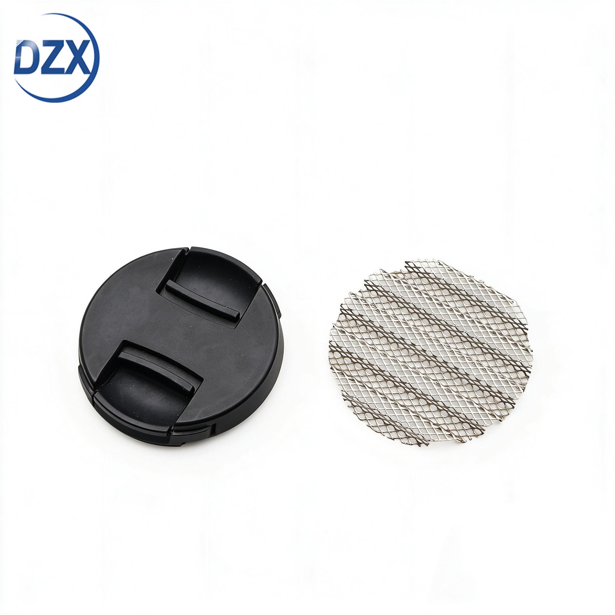


Pure Nickel Corrugated Mesh — Gas-Liquid Two-Phase Flow Optimization for High-Current-Density Electrolyzer Operation
Product Attributes: N4 N6 Ni200 Ni201
Certificates: ISO9001 CE RoHS
Customization available based on provided drawings and samples.
 0
0Product Attributes: N4 N6 Ni200 Ni201
Certificates: ISO9001 CE RoHS
Customization available based on provided drawings and samples.

Pure Nickel Corrugated Mesh — Gas-Liquid Two-Phase Flow Optimization for High-Current-Density Electrolyzer Operation

Nickel-Only Facility | Since 2002 | N4/N6/Ni200 | Bubble-Optimized | Free 5-Sheet Sample
At 0.5 A/cm², gas bubbles in an alkaline electrolyzer are a minor nuisance. At 2 A/cm², they are the dominant performance limitation. The anode produces oxygen at roughly 0.6 mL per minute per square centimeter. The cathode produces hydrogen at twice that rate. These bubbles do not simply float away — they accumulate in the electrode gap, block fresh electrolyte from reaching the catalyst surface, increase the ohmic resistance of the electrolyte by displacing conductive liquid with non-conductive gas, and create an additional overpotential known as the bubble overpotential. At Jiangsu DZX Alloy Co., Ltd., we design corrugated nickel mesh flow fields specifically to manage this two-phase flow problem. The corrugation channel geometry — pitch, depth, profile shape, and channel orientation — is engineered to guide gas bubbles out of the electrode gap while drawing fresh electrolyte in. Our mesh is a flow management device first and a current collector second — because at the current densities that make green hydrogen economically viable, gas management determines cell performance more than electrical conductivity ever will.

| Current Density | Gas Void Fraction in Electrode Gap | Bubble Overpotential Contribution | Dominant Loss Mechanism |
|---|---|---|---|
| 0.3 A/cm² | ~5–10% | ~10–20 mV | Kinetic overpotential (catalyst activity) |
| 0.6 A/cm² | ~15–25% | ~30–60 mV | Kinetic + ohmic share dominance equally |
| 1.0 A/cm² | ~25–40% | ~60–120 mV | Bubble overpotential begins to dominate |
| 1.5 A/cm² | ~35–55% | ~100–200 mV | Bubble overpotential is the single largest loss — exceeding kinetic and ohmic combined |
| 2.0 A/cm² | ~45–65% | ~150–300 mV | Bubble overpotential dominant. Cell voltage diverges sharply from the Tafel + ohmic prediction. Without engineered gas management, the cell cannot sustain this current density. |
The implication is clear: an electrolyzer designed for 1.5 A/cm² or above cannot rely on buoyancy-driven bubble release through a random mesh structure. It requires engineered flow channels that actively separate gas from liquid and transport each phase where it belongs. This is the function of corrugated mesh — and the corrugation geometry determines how well it performs that function.

| Geometry Parameter | Flow Physics It Controls | Optimization Guidance |
|---|---|---|
| Channel depth (amplitude) | Determines the cross-sectional area available for gas flow. At 2 A/cm², the gas production rate requires a minimum channel cross-section to avoid bubble coalescence into slugs that block the channel entirely. | Minimum channel depth for 2 A/cm² operation: approximately 0.8 mm. Below this, slugs form and the channel oscillates between blocked and open — creating pressure pulsations that damage the membrane. Typical range: 0.8–2.5 mm. |
| Channel width (pitch / 2 for trapezoidal) | Determines the hydraulic diameter of each flow channel, which controls the gas bubble rise velocity and the liquid down-flow. Channels narrower than ~1.5 mm hydraulic diameter promote bubble coalescence; channels wider than ~4 mm hydraulic diameter allow gas-liquid separation within the channel (gas rises along the channel ceiling, liquid descends along the floor — counter-current flow). | Counter-current flow within each channel is the ideal regime: gas rises, liquid descends, they do not block each other. Achieved at approximately 2–4 mm channel width with adequate depth. For sinusoidal corrugation, effective channel width is approximately pitch / 2.5. |
| Channel orientation | Vertical channels: buoyancy drives gas upward — ideal for single-phase gas removal. Inclined channels: gas slides along the upper channel wall — good for diagonal flow designs. Horizontal channels: gas accumulates in pockets along the channel ceiling — worst case for gas removal unless forced convection is used. | Vertical orientation is standard: channels run from bottom to top of the cell. Gas produced along the entire channel length rises and exits at the top manifold. Liquid electrolyte enters at the bottom manifold and flows upward, counter-current to the gas, or enters through the mesh plane from a distribution channel. |
| Profile shape (wall angle) | The angle of the channel wall relative to vertical determines how gas bubbles interact with the wall. Vertical walls (rectangular channel): bubbles rise freely in the center but can adhere to the wall — creates stagnant bubble zones. Inclined walls (trapezoidal): bubbles slide along the inclined surface — fewer stagnant zones, more efficient gas clearance. | Trapezoidal channels with wall angle 15–30° from vertical provide the best balance of gas clearance and mechanical stability. Wall angles steeper than 10° approach rectangular behavior — stagnant zones form. Angles shallower than 30° reduce channel cross-section for a given pitch. |
| Open area within the mesh plane | Through-plane permeability: electrolyte can also flow through the mesh openings between channels, not just along the channels. This provides a secondary flow path that redistributes electrolyte from well-supplied regions to starved regions — smoothing out flow maldistribution. | Woven substrate with 30–50 mesh and 0.15–0.25 mm wire provides adequate through-plane permeability for redistribution without excessive pressure loss. Expanded substrate with 40–55% open area provides higher through-plane permeability — beneficial for designs where the primary electrolyte supply is through-plane rather than along the channels. |
 How We Validate — Flow Visualization and Pressure Drop Measurement
| Measurement | Method | What It Tells You |
|---|---|---|
| Single-phase pressure drop | Water flow through a mesh sample compressed between transparent plates at your stack compression pressure. Differential pressure transducer measures ΔP across the sample at flow rates corresponding to your cell operating conditions. | The baseline hydraulic resistance of the mesh flow field. Used to calculate the pumping power required to circulate electrolyte through the cell. If the pressure drop is too high, electrolyte circulation power reduces the net system efficiency — offsetting the electrochemical gains from the mesh flow field. |
| Two-phase flow visualization | Transparent cell with mesh sample, water + dispersed air bubbles simulating the gas production rate at your target current density. High-speed video captures bubble behavior: coalescence, channel blockage, stagnant zones, gas clearance time. | Visual confirmation that the corrugation geometry produces the intended flow regime. Identifies stagnant bubble zones that would become hot spots in a real cell. Validates that gas clearance time is faster than gas production time — the cell does not accumulate gas over time. |
| Gas hold-up measurement | The volume fraction of gas in the electrode gap under steady flow conditions. Measured by the change in electrical conductivity of the gap — gas is non-conductive, so higher gas hold-up reduces the measured conductance between two sensing electrodes. | The gas hold-up directly correlates with the bubble overpotential. Reducing gas hold-up from 45% to 30% at 1.5 A/cm² can reduce the bubble overpotential by approximately 30–50 mV — one of the largest single improvements available in alkaline electrolyzer cell design. |
Flow characterization data package: For customers developing cell designs targeting >1 A/cm², we offer a flow characterization package covering single-phase ΔP, two-phase visualization, and gas hold-up measurement on your specified mesh geometry. The data package supports your CFD model validation and provides experimental confirmation that your corrugation design achieves the intended flow regime.

Designed for the dominant loss mechanism at your current density — At 0.5 A/cm², you need good electrical contact. At 2 A/cm², you need engineered gas-liquid separation — because bubble overpotential is 2–5× larger than all other losses combined. Our corrugated mesh is designed for the current density you actually operate at — not the current density where mesh is just a current collector.
Corrugation geometry informed by flow physics, not by available tooling — Most corrugated mesh suppliers offer whatever profiles their existing gear-former can produce. At DZX, the flow physics determines the geometry, and the tooling is made to match. If your CFD model says you need 3.2 mm pitch with 1.4 mm depth and trapezoidal walls at 22° — that is the die set we cut. We do not ask you to adjust your flow field design to match our tooling inventory.
Counter-current flow within each channel — the ideal regime — In a properly designed channel, gas bubbles rise along the upper wall while liquid electrolyte descends along the lower wall. They pass each other without blocking. This is counter-current two-phase flow — the most efficient regime for simultaneous gas removal and liquid supply. Our trapezoidal profile with controlled wall angle promotes this regime across a wide range of gas production rates.
Validated, not assumed — flow data from your mesh geometry — A CFD model of two-phase flow in a corrugated channel is only as good as its input assumptions: bubble size, wall contact angle, turbulence model. Our flow visualization gives you direct experimental evidence of the actual flow regime in your mesh geometry. You can validate your CFD model against our data — then use the validated model to optimize further.
Stagnant zones eliminated — because they become hot spots — In a poorly designed mesh, bubbles accumulate where the channel geometry creates a recirculation zone or a wall adhesion site. These stagnant bubbles do not contribute to gas production but they do block electrolyte access. The electrode area behind a stagnant bubble is starved — local current density drops — the surrounding area carries more current — the surrounding area degrades faster. Flow visualization identifies these zones so that the geometry can be adjusted before the stack is built.
Nickel surface wettability — consistent, because the processing is consistent — The contact angle between a gas bubble and the mesh surface determines whether the bubble sticks or slides. This contact angle depends on the nickel surface chemistry — specifically, on whether the surface is clean nickel, nickel oxide, or nickel contaminated with iron or carbon. Our nickel-only processing and controlled-atmosphere annealing produce a consistent surface chemistry — which produces a consistent contact angle — which produces consistent bubble behavior. Batch to batch. Year to year.
 About DZX — Flow Engineering Through Metallurgical Control
Jiangsu DZX Alloy Co., Ltd. was founded in 2002 and has manufactured pure nickel products — exclusively — for over two decades. This focus means that when we design a flow field, we understand not only the fluid dynamics but also the surface that the fluid contacts. The nickel surface after controlled-atmosphere annealing. The nickel surface after extended exposure to 30% KOH at 80°C. The nickel surface after thousands of hours of oxygen evolution at the anode. Each of these surfaces has a different wettability — and therefore different bubble behavior. A flow field designed for fresh nickel will not perform the same after the surface has oxidized during the first 100 hours of operation. We account for this in the geometry — designing channels that function correctly with the oxidized surface, not just the fresh surface.
12,000 m² nickel-only facility — melting, wire drawing, strip rolling, weaving, expanding, corrugating, annealing. Consistent nickel surface from ingot to finished flow field.
Flow characterization capability — single-phase ΔP, two-phase flow visualization, gas hold-up measurement. Data from your mesh geometry at your flow conditions.
Custom corrugation tooling — pitch 2.0–8.0 mm, depth 0.5–3.0 mm, sinusoidal or trapezoidal profile. Die sets cut to your flow field design, not selected from our inventory.
ISO9001 with full melt-to-mesh traceability. SGS-accredited. Flow characterization data package available for cell development programs.
 Chemical Composition — Four Pure Nickel Grades for Flow Field Applications
Chemistry certified from ingot through finished mesh. Surface chemistry consistent with bulk — verified in a nickel-only processing environment. Grade selection for flow field applications: primary consideration is surface stability under anodic or cathodic operating conditions.
| Element (%) | N4 | N6 | Ni200 | Ni201 |
|---|---|---|---|---|
| Ni+Co | ≥99.9 | ≥99.5 | — | — |
| Ni | — | — | ≥99.2 | ≥99.0 |
| Fe | ≤0.04 | ≤0.1 | ≤0.4 | ≤0.4 |
| Cu | ≤0.015 | ≤0.1 | ≤0.25 | ≤0.25 |
| C | ≤0.01 | ≤0.1 | ≤0.15 | ≤0.02 |
| Si | ≤0.03 | ≤0.1 | ≤0.35 | ≤0.35 |
| Mn | ≤0.002 | ≤0.05 | ≤0.35 | ≤0.35 |
| S | ≤0.001 | ≤0.005 | ≤0.01 | ≤0.01 |
Flow field grade recommendation: N6 is the most common choice for corrugated flow fields — the purity level is sufficient for surface wettability stability over the electrode life. N4 is specified when the flow field also serves as the electrode substrate (catalyst-coated mesh) and maximum electrochemical purity is required. Ni201 is specified for flow fields in elevated-temperature ALK designs above 90°C.
| Mesh type | Corrugated — woven or expanded nickel substrate. Sinusoidal or trapezoidal profile. |
| Substrate wire (woven) | 0.10–0.40 mm — all four nickel grades. Mesh count 10–200. |
| Substrate strand (expanded) | 0.4–0.8 mm — all four nickel grades. Open area 30–65%. |
| Corrugation pitch | 2.0–8.0 mm — custom per flow field design |
| Corrugation depth | 0.5–3.0 mm — custom per flow field design |
| Profile shape | Sinusoidal or trapezoidal with specified wall angle — custom per drawing |
| Channel orientation | Vertical (standard), inclined, or custom per drawing |
| Sheet dimensions | Custom L × W — laser or shear cut. Manifold openings punched per drawing. |
| Post-treatment | Solution annealed — zero residual stress, consistent surface chemistry, stable wettability |
| Flow characterization | Single-phase ΔP, two-phase flow visualization, gas hold-up measurement — available per request |
| Flow-Relevant Attribute | Verification Method | Documentation |
|---|---|---|
| Corrugation geometry | Pitch, depth, wall angle — optical measurement per sheet lot. Geometry determines the flow regime. Deviation changes the bubble behavior. | Dimensional inspection report — pitch, depth, wall angle per lot |
| Surface condition | Water break test — verifies clean nickel surface. Visual at 5× — no contamination, no staining, no oxide discoloration. Wettability depends on surface chemistry. | Surface cleanliness cert per lot |
| Chemistry | OES per ingot. Fe, Cu, trace elements verified. Surface Fe stability affects long-term wettability. | EN 10204 3.1 MTC |
| Annealing condition | Hardness per lot. Grain size per lot. Full recrystallization confirmed. Consistent surface chemistry requires consistent annealing. | Hardness report. Grain size report. |
| Sheet dimensions | L × W ±0.5 mm. Edge tactile sweep per sheet. Flatness verification. | Dimensional report + edge inspection sign-off + flatness report |
| Flow data (if requested) | Single-phase ΔP at specified flow rate. Two-phase visualization images at specified gas production rate. Gas hold-up measurement. | Flow characterization report |
Third-party verification by SGS, BV, or TÜV. Free 5-sheet sample with geometry verification data. Flow characterization package available for cell development programs.
| Geometry protection | Corrugated sheets are nested — peaks of one sheet align with valleys of the adjacent sheet, separated by a single layer of acid-free tissue. This prevents the stack weight from compressing or deforming the corrugation profile during transit. Stacked flat between rigid backing boards. |
| Surface protection | Nickel-contact-only handling. Vacuum sealed with desiccant in barrier film. Surface chemistry — and therefore wettability — is preserved from our annealing furnace to your cell assembly. |
| Crating | Seaworthy plywood crate with internal bracing contacting backing boards, not mesh. Labeled with grade, heat number, corrugation geometry, sheet dimensions, lot number, and DZX traceability code. |
| Documentation | EN 10204 3.1 MTC + dimensional report + surface cleanliness cert + edge inspection sign-off + flow characterization report (if requested) + packing list. |
| Sample MOQ | 5 sheets — free with geometry verification data. Evaluate our corrugation accuracy and surface quality against your current mesh. |
| Production MOQ | 50 sheets per drawing number. Custom die sets amortized across first production order. |
| Lead Time | Existing tooling: 2 weeks trial, 4 weeks production. New die set: add 3–4 weeks. Flow characterization: add 2–3 weeks. |
| Shipping | Air (DHL, FedEx) for trial; sea (FCL) for production. Geometry-preserving packaging validated for 6-week ocean transit. |
| Payment | T/T for trial; T/T or L/C at sight for production. |

At what current density does engineered gas management become necessary?
Below 0.5 A/cm², natural buoyancy-driven bubble rise through a flat or randomly structured mesh is generally sufficient — the gas production rate is low enough that bubbles escape before accumulating. Between 0.5 and 1.0 A/cm², engineered channels begin to provide measurable benefit — typically 15–30 mV reduction in bubble overpotential. Above 1.0 A/cm², engineered channels are necessary — without them, the gas void fraction exceeds 35% and the cell voltage diverges sharply from the electrochemical prediction. If your stack target is above 1 A/cm², corrugated mesh with two-phase-flow-optimized geometry is not optional.
How do I select the right channel depth for my current density?
As a starting point: channel depth (mm) ≈ 0.4 × (current density in A/cm²) + 0.4. For 1.5 A/cm²: depth ≈ 1.0 mm. For 2.0 A/cm²: depth ≈ 1.2 mm. This is a rule of thumb based on the gas production rate per unit electrode area. The exact optimum depends on your channel pitch, cell height (taller cells accumulate more gas toward the top), and whether your cell design uses forced electrolyte circulation or natural convection. We recommend testing 2–3 depths in single-cell configuration and measuring the cell voltage vs current density curve — the optimum depth produces the lowest voltage at your target current density.
Does the mesh substrate affect gas management, or only the corrugation?
Both. The corrugation provides the primary gas escape channels. The mesh substrate — woven or expanded — determines the through-plane permeability: how easily gas bubbles can enter the channels from the electrode surface. If the substrate is too dense (very fine mesh, low open area), bubbles are trapped between the electrode and the mesh — they cannot reach the channels to escape, regardless of how well the channels are designed. Woven substrate with 30–50 mesh and 0.15–0.25 mm wire typically provides the best balance of through-plane permeability and electrical contact. Expanded substrate with 40–55% open area provides higher permeability and is preferred for designs where the mesh is directly adjacent to the electrode with no separate gas diffusion layer.
How do you account for surface wettability changes during the first 100 operating hours?
Fresh annealed nickel is hydrophilic — water spreads on the surface, and gas bubbles have a high contact angle and tend to detach easily. After exposure to 30% KOH at 80°C and anodic polarization, the surface forms a thin nickel oxide/hydroxide layer that is less hydrophilic. Gas bubbles adhere more strongly to this oxidized surface — they are harder to remove. Our flow visualization uses pre-conditioned mesh samples — oxidized in KOH at operating temperature for 100 hours before testing — so that the observed bubble behavior represents the steady-state operating condition, not the transient fresh-surface condition. This is important: a flow field optimized for fresh nickel will underperform after the first week of operation.
Can you model the expected bubble overpotential reduction for our specific cell design?
We can provide the experimental gas hold-up data for your mesh geometry at your flow conditions. You input this data into your cell voltage model — specifically, into the ohmic loss term where the effective electrolyte conductivity is reduced by the gas void fraction. The model then predicts the cell voltage with and without the corrugated flow field at each current density. The difference is the estimated bubble overpotential reduction. We recommend validating the model prediction with a single-cell test using the optimized mesh geometry. Most customers see good agreement between the hold-up-based prediction and the measured cell voltage improvement.
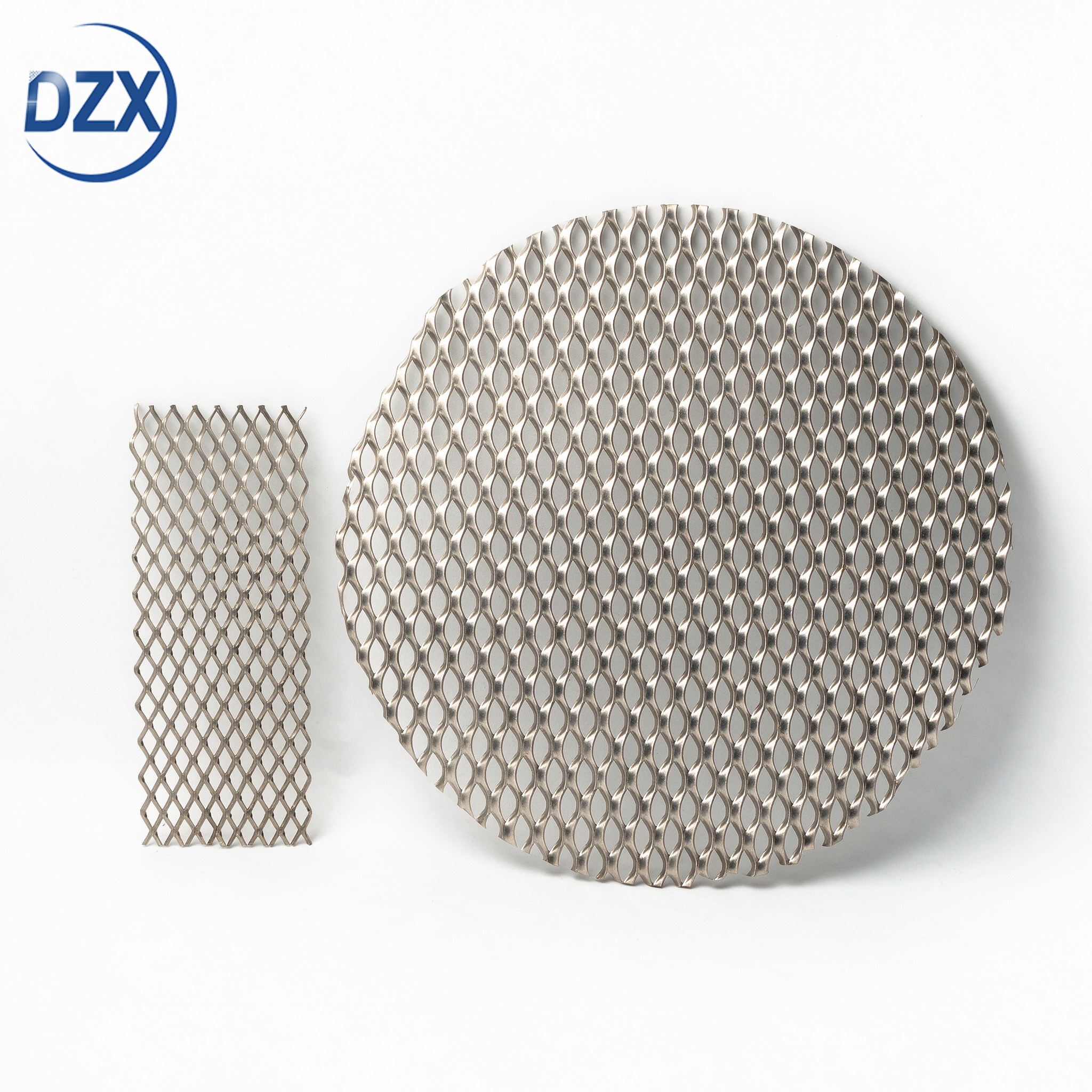


E-mail: dzx@dlx-alloy.com
Mobile: +8619906119641
Tel: 0086-19906119641
WhatsApp: +86-19906119641
Add: NO.32 West Taihu Road, Xinbei District, Changzhou, Jiangsu


